

Solar Street Light Design for Municipal Roads: A Lumen Planning, Pole Layout, and Battery Autonomy Guide
Municipal engineers and EPC contractors increasingly encounter solar road lighting as a default option in off-grid or grid-constrained corridors. Yet misspecifying lumen output, pole geometry, or battery reserve days remains the leading cause of underperforming installations. This guide translates IEC standards, photometric principles, and real-world autonomy calculations into actionable design parameters for municipal solar lighting projects.
The Real Challenge in Municipal Solar Lighting Projects
Off-grid road lighting has expanded rapidly across emerging markets and rural municipalities. According to IRENA's Renewable Power Generation Costs 2023 report, the levelised cost of solar-based systems has fallen over 80% since 2010, making solar road lighting cost-competitive with grid extension in corridors where grid connection cost exceeds approximately USD 10,000–15,000 per km. The Global Off-Grid Lighting Association (GOGLA) estimates that over 130 million off-grid lighting units were sold globally between 2015 and 2022, with municipal-grade systems representing a fast-growing segment.
Despite this growth, a significant share of installed solar street lights underperform or fail prematurely. The core design errors observed across municipal projects include:
- Lumen mismatch: Specifying fixtures by wattage instead of illuminance requirements, leading to over- or under-lit road sections
- Geometry neglect: Defaulting to arbitrary pole heights and spacing without running an ISO 13032 or CIE 115 photometric verification
- Shallow battery reserves: Sizing battery autonomy for average irradiance rather than worst-case consecutive overcast days, resulting in early-night shutoffs during winter months
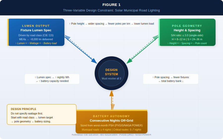
These three failure vectors are interrelated. A shorter pole requires higher lumen output to achieve the same road illuminance. A denser pole grid can tolerate lower lumen per fixture but increases civil works cost. Battery sizing directly governs how many nights the system can sustain full output without solar recharge.
Designing a municipal solar road lighting system means resolving all three variables simultaneously—not sequentially.
Lumen Planning: Starting from Road Classification, Not Wattage
Solar street light design should begin with the target illuminance level mandated by the applicable road lighting standard, not with a fixture wattage catalog entry.
Applicable Standards and Illuminance Classes
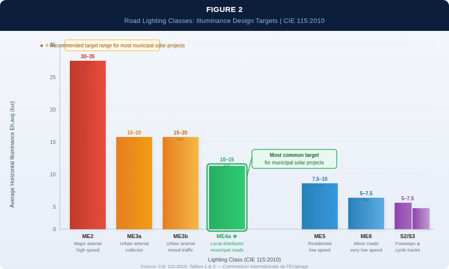
The most widely referenced international standard for road lighting is CIE 115:2010 (Lighting of Roads for Motor and Pedestrian Traffic), which defines lighting classes based on traffic speed, traffic mix, and road complexity. For municipal roads, the following classes apply in the majority of projects:
| Lighting Class | Avg. Road Surface Luminance (Lav) | Avg. Horizontal Illuminance (Eh,avg) | Typical Application |
|---|---|---|---|
| ME3a / ME3b | 1.0 cd/m² | ~15–20 lux | Main urban arterials, collector roads |
| ME4a | 0.75 cd/m² | ~10–15 lux | Local distributor roads |
| ME5 / ME6 | 0.50 cd/m² | ~7.5–10 lux | Residential roads, low-speed lanes |
| S2 / S3 | — | 5–7.5 lux avg | Footways, cycle tracks adjacent to roads |
Source: CIE 115:2010, Table 1 and Table 3
For most municipal road projects in developing regions, the ME4a to ME3b range (10–20 lux average horizontal illuminance) is the practical design target. Projects specifying ME2 or above (≥ 30 lux) at standard pole spacing with solar power will require substantially larger panel and battery systems, and should be evaluated carefully for lifecycle cost.
Translating Illuminance to Lumen Requirements
The required luminous flux (lm) from each fixture is derived from:
Required lumens per fixture ≈ (Target Eh × Road Area per pole) ÷ Utilisation Factor (UF)
A representative municipal road calculation:
- Road width: 7 m (two-lane local road)
- Pole spacing: 30 m (single-side arrangement)
- Road area per pole: 7 × 30 = 210 m²
- Target Eh,avg: 12 lux (ME4a class)
- UF (ratio of flux reaching the road surface): typically 0.28–0.40 for a well-designed Type II or Type III distribution luminaire at 8 m mounting height
Required output = (12 × 210) ÷ 0.33 ≈ 7,636 lm per fixture
A fixture rated at 8,000–9,000 lm (delivered, after thermal derating at operating temperature) would meet this requirement with a modest maintenance factor allowance. This corresponds to approximately 60–75 W in a high-efficacy LED system (≥120 lm/W system efficacy).
Critical note: Always specify luminous flux in delivered lumens at the road surface, not raw LED lumen output. Optical losses (lens, housing, soiling factor) typically reduce effective output by 15–25% relative to the LED chip rating.
Pole Spacing and Height: Photometric Geometry for Solar Road Lighting
In grid-connected road lighting, pole spacing is often driven by civil economics. In solar road lighting design, pole geometry has a direct and often underestimated effect on energy system sizing.
The Height-Spacing Relationship
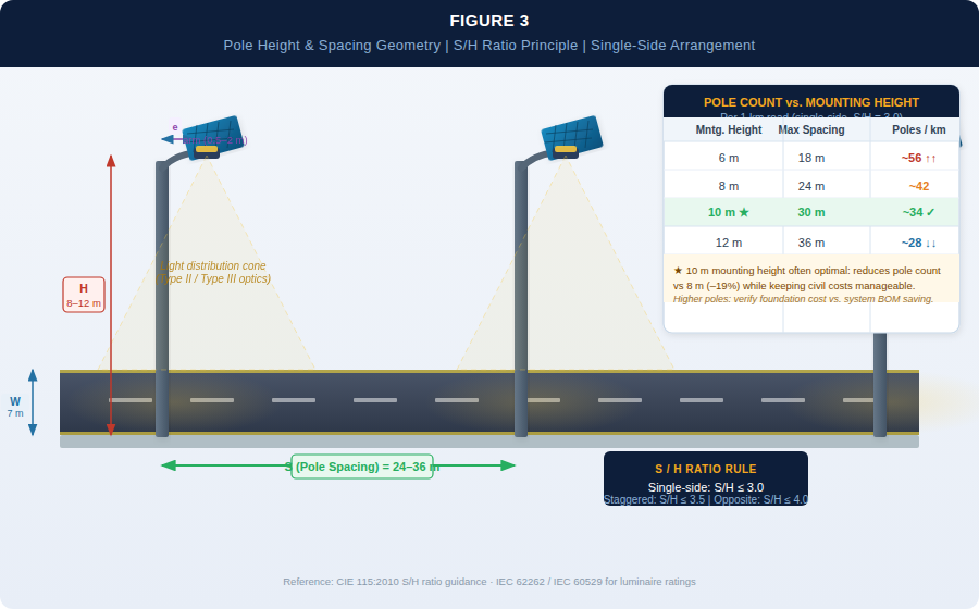
The fundamental constraint is the S/H ratio (spacing-to-mounting-height ratio). For uniform illuminance distribution on a road:
- Single-side arrangement: S/H ≤ 3.0 recommended; ≤ 2.5 for higher uniformity
- Staggered bilateral: S/H ≤ 3.5
- Opposite bilateral: S/H ≤ 4.0 (requires wider road width ≥ 9 m)
At a mounting height of 8 m with S/H = 3.0, maximum spacing is 24 m. At 10 m height, spacing can extend to 30 m under the same ratio.
Why does this matter for solar systems? Every additional meter of pole spacing reduces the number of poles per kilometre, directly lowering the total number of solar panels, batteries, and fixtures required. For a 1 km road section:
| Mounting Height | Max Spacing (S/H=3) | Poles per km (single-side) | Relative System Cost Index |
|---|---|---|---|
| 6 m | 18 m | ~56 | High |
| 8 m | 24 m | ~42 | Moderate-High |
| 10 m | 30 m | ~34 | Moderate |
| 12 m | 36 m | ~28 | Lower (civil cost rises) |
At 10–12 m heights on arterial roads, the reduction in pole count (and associated system BOM) often justifies the higher pole and foundation cost—though this must be verified per project with a full civil-to-system cost trade-off.
Overhang Arm Length
For roads wider than 9 m, engineers typically specify an overhang arm of 1.5–2.0 m to bring the luminaire closer to the road centreline. A 1.5 m arm on a 10 m pole effectively raises the optical offset and improves coverage of the opposite lane without increasing pole height. This can allow the use of Type II rather than Type III distribution optics, improving uniformity.
Battery Autonomy: The Most Frequently Underspecified Parameter
Battery autonomy—the number of consecutive nights a solar street light system can operate at full output without solar recharge—is the defining reliability parameter for municipal solar lighting, particularly in regions with pronounced rainy seasons or winter cloud cover.
Establishing the Design Autonomy Requirement
Autonomy is not a fixed number; it is a function of local irradiance variability. The correct methodology is:
- Retrieve monthly irradiation data for the project location from PVGIS (EU Joint Research Centre) or NASA POWER (both free, publicly accessible)
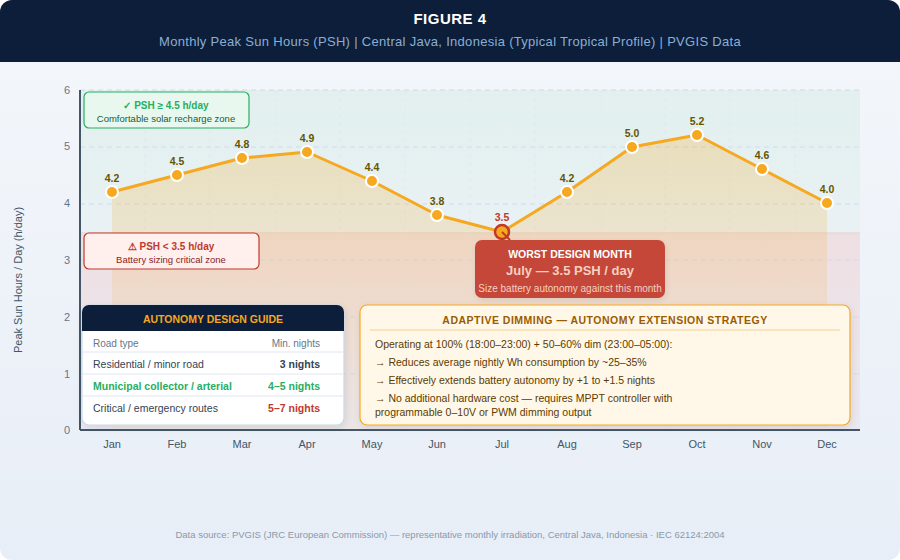
- Identify the worst solar month (typically November–January for northern hemisphere; May–July for southern hemisphere tropical zones)
- Calculate average peak sun hours (PSH) for the worst month
- Size battery for N consecutive overcast days based on project risk tolerance
Industry guidance from IEC 62124 (Photovoltaic (PV) Stand-Alone Systems – Design Verification) and standard off-grid design practice suggests:
- Residential / low-criticality roads: 3 autonomous nights minimum
- Municipal collector and arterial roads: 4–5 autonomous nights
- Critical corridors (hospital access, emergency routes): 5–7 autonomous nights
LiFePO₄ vs. VRLA for Municipal Autonomy Requirements
The battery chemistry choice significantly affects autonomy design:
| Parameter | LiFePO₄ (Lithium Iron Phosphate) | VRLA / AGM (Lead-Acid) |
|---|---|---|
| Usable DoD | 80–90% | 40–50% |
| Cycle life (to 80% capacity) | 2,000–3,000+ cycles | 500–800 cycles |
| Self-discharge rate | ~2–3% per month | ~5–10% per month |
| Weight (for equivalent storage) | ~0.4× VRLA | Baseline |
| Performance in high heat (>35°C) | Moderate degradation, BMS-managed | Accelerated degradation |
| Upfront cost premium | 1.8–2.5× VRLA | Baseline |
| Recommended replacement cycle | 8–12 years | 3–5 years |
| Net TCO advantage (10-year horizon) | Typically favourable at ≥4 autonomous nights | Favourable only at <3 nights in mild climates |
Data ranges based on published cycle life specifications from major LFP cell manufacturers and IEEE 1013 battery sizing guidelines
When projects require 4+ nights of autonomy and operate in ambient temperatures above 30°C (common across South and Southeast Asia, Sub-Saharan Africa, and the Middle East), LiFePO₄ chemistry is generally the technically justified choice on a 10-year TCO basis, despite the higher initial cost.
A Note on Smart Dimming as an Autonomy Extension Strategy
A common engineering approach to extending effective battery autonomy is adaptive dimming scheduling: operating at 100% output during peak pedestrian hours (e.g., 18:00–23:00) and reducing to 50–60% during low-traffic hours (e.g., 23:00–05:00). This reduces average nightly energy consumption by approximately 25–35%, effectively extending autonomy by 1–1.5 nights without increasing battery capacity. Most microcontroller-based solar charge controllers support programmable dimming profiles via 0–10V or PWM signal.
Design Decision Tool: Calculation Example and Configuration Checklist
Worked Example: ME4a Road in Southeast Asia
Project Parameters:
- Location: Central Java, Indonesia (PSH worst month ≈ 3.5 h/day based on PVGIS data for the region)
- Road class: Local distributor, ME4a target (12 lux average)
- Road width: 7 m, single-side pole arrangement
- Mounting height: 8 m, arm length 1.0 m
- Pole spacing: 25 m (S/H = 3.1, within acceptable range)
- Required fixture output: ~8,000 lm (from lumen planning calculation above)
- System LED efficacy: 130 lm/W → fixture wattage ≈ 62 W
- Operating hours: 11 h/night (sunset to sunrise average)
- Dimming profile: 100% for first 5 h, 60% for remaining 6 h
- Effective nightly energy: (62 × 5) + (37 × 6) = 310 + 222 = 532 Wh/night
- Autonomy requirement: 4 nights (municipal collector road standard)
Battery Sizing:
- Total energy for 4 nights: 532 × 4 = 2,128 Wh
- LiFePO₄ usable DoD: 85% → required nominal capacity: 2,128 ÷ 0.85 = 2,503 Wh
- At 25.6 V (8S LFP): 2,503 ÷ 25.6 ≈ 98 Ah (specify 100 Ah nominal)
Solar Panel Sizing:
- Daily energy consumption: 532 Wh
- System efficiency (controller + wiring): 0.85
- Required panel output: 532 ÷ (3.5 × 0.85) = 179 W → specify 200 W monocrystalline panel
Summary Configuration per Pole:
- LED fixture: 60–65 W, 8,000 lm delivered, Type II/III optics
- Solar panel: 200 W monocrystalline
- Battery: LiFePO₄ 100 Ah / 25.6 V with integrated BMS
- Charge controller: MPPT, ≥ 20 A, programmable dimming output
Municipal Solar Lighting Design Checklist
Use the following checklist before finalising a solar road lighting specification:
- Road classification confirmed: Lighting class (ME3/ME4/ME5/S2) defined per CIE 115 or local standard
- Illuminance target verified by photometric simulation: DIALux or AGi32 model run for proposed pole spacing and height, confirming Eh,avg and uniformity ratio (Uo ≥ 0.40 for ME class)
- Lumen specification stated as delivered lumens at road surface, not chip lumens or rated wattage
- Local irradiation data retrieved: Worst-month PSH confirmed via PVGIS or NASA POWER for project coordinates
- Battery autonomy nights defined: ≥ 3 nights for minor roads; ≥ 4–5 nights for arterial and collector roads
- Battery chemistry justified: LiFePO₄ evaluated for projects with ≥ 4 autonomy nights or ambient T > 35°C
- Dimming schedule documented: Profile defined, charge controller compatibility confirmed
- IP rating confirmed: Luminaire IP66 minimum; battery enclosure IP55 minimum for tropical/humid climates
- IK rating checked: IK08 or above for luminaires in public-access areas
- Surge protection specified: SPD Type 2 (≥ 10 kA) on luminaire input for lightning-prone regions
- Warranty and cycle life documentation requested: Minimum 3-year system warranty; battery cycle life certification at specified DoD
Conclusion: Three Numbers That Define Your Design
A well-executed municipal solar lighting design ultimately converges on three verifiable numbers: the delivered lumen output of the fixture (determined by road class), the S/H ratio governing pole geometry (driving civil and system cost), and the battery autonomy nights (sized against worst-month irradiance, not annual averages).
When all three are specified with engineering rigour rather than catalog defaults, solar road lighting consistently delivers reliable performance across a 10–15 year service life. When any one is underspecified, the failure mode is predictable and expensive to correct post-installation.
For projects where ambient temperatures exceed 30°C and road class requires ME4a or above, the combination of LiFePO₄ storage, MPPT charge control, and adaptive dimming scheduling typically represents the lowest 10-year TCO configuration—provided the upfront capital is available or financeable.
If you need a system configuration assessment tailored to your project's road class, GPS coordinates, and budget envelope, the technical team at Infralumin street light manufacturer can provide a customised design proposal including photometric simulation reports and BOM-level cost estimation.
References
- IRENA · Renewable Power Generation Costs 2023 · International Renewable Energy Agency, 2024
- GOGLA · Global Off-Grid Solar Market Report · Annual Sales and Impact Data, 2022
- CIE · CIE 115:2010 – Lighting of Roads for Motor and Pedestrian Traffic · Commission Internationale de l'Éclairage, 2010
- IEC · IEC 62124:2004 – Photovoltaic (PV) Stand-Alone Systems – Design Verification · International Electrotechnical Commission, 2004
- IEEE · IEEE 1013-2019 – Recommended Practice for Sizing Lead-Acid Batteries for Stationary Applications · IEEE Standards Association, 2019
- European Commission Joint Research Centre · PVGIS (Photovoltaic Geographical Information System) · https://re.jrc.ec.europa.eu/pvg_tools/
- NASA · NASA POWER – Prediction of Worldwide Energy Resources · https://power.larc.nasa.gov/

Zhongshan Lumin Technology Co., Ltd. is a renowned high-tech enterprise specializing in the research, development, and manufacturing of industrial LED lights.
Contact
@2026 Zhongshan Lumin Technology Co., Ltd.