

Key Components of a Commercial Solar Street Lighting System
A solar street lighting project that performs reliably over a 10-year service life and one that fails within 18 months can look identical on paper—same panel wattage, same fixture lumen output, same quoted price. The difference almost always lies in how the core components are specified, integrated, and verified. This guide breaks down the six critical subsystems of a commercial solar street lighting system, explains the engineering logic behind each specification decision, and provides a practical framework for procurement teams to evaluate proposals objectively.
Why Solar Street Light Component Specification Matters More Than Ever
Global shipments of solar street lights reached an estimated 20 million units in 2022 and continue to expand across Southeast Asia, Africa, the Middle East, and Latin America—driven by the combination of falling PV module costs, rising grid-extension expenses, and municipal sustainability mandates. Yet field failure rates remain disproportionately high in the commercial segment. The International Energy Agency's 2023 off-grid lighting market report noted that sub-standard battery chemistry and undersized solar panels are the two most frequently cited causes of premature system failure in public-sector lighting deployments in emerging markets (IEA, 2023).
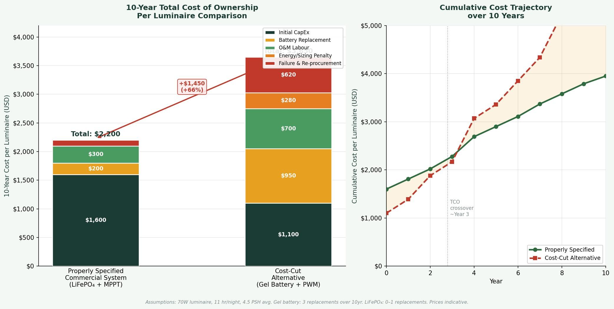
This pattern matters to EPC contractors and municipal procurement managers for a specific reason: the capital expenditure difference between a properly specified commercial solar LED system and a cost-cut alternative can be as little as 15–25%, yet the total cost of ownership (TCO) gap over 10 years—when maintenance visits, battery replacements, and reputational project failure are factored in—often exceeds 60%. Engineers generally recommend evaluating solar lighting proposals on a 7–10 year TCO basis rather than unit cost alone.
The Six Core Components of a Commercial Solar Street Lighting System
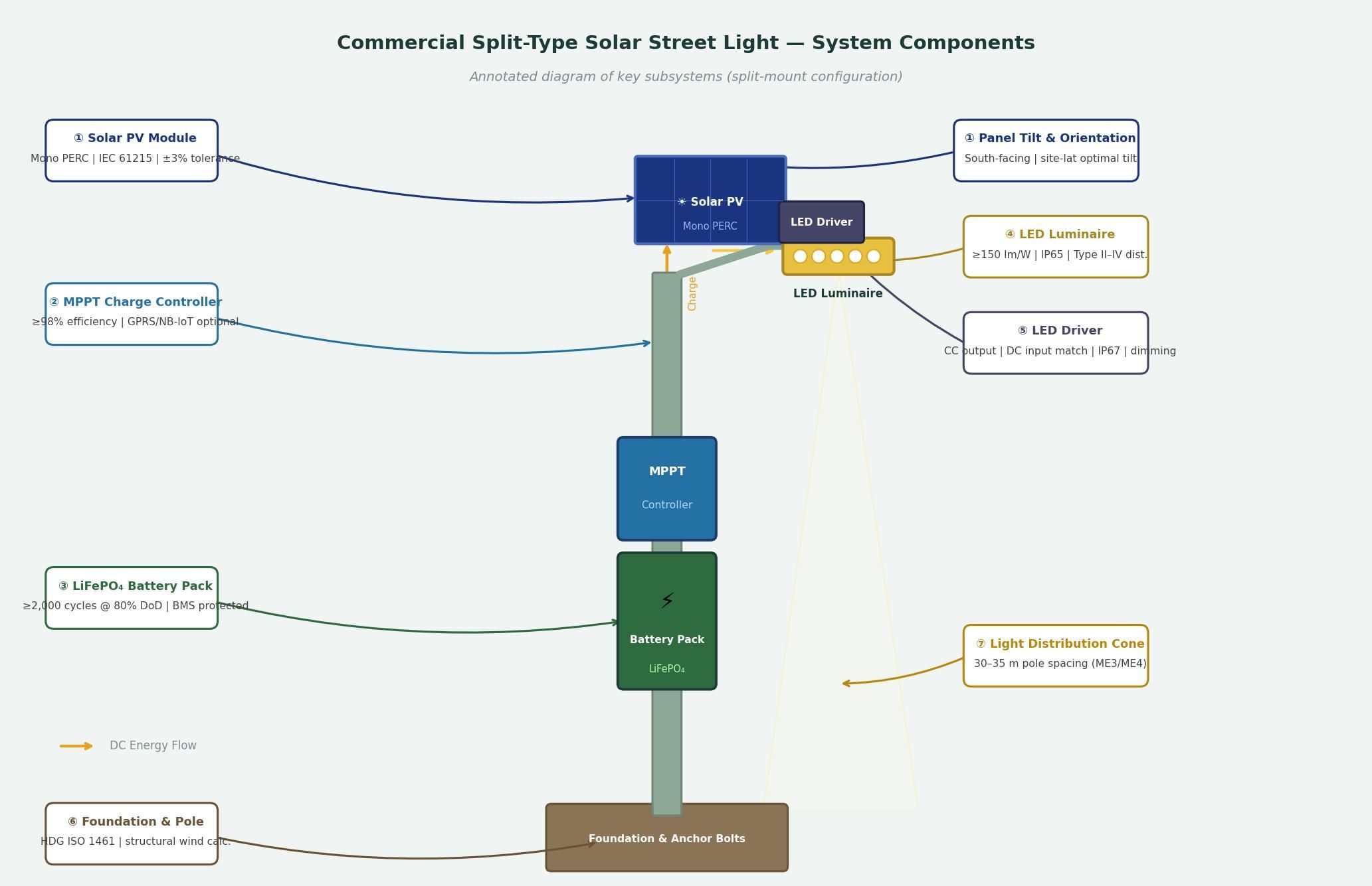
A commercial solar street lighting system is not a single product—it is an integrated energy system composed of six interdependent subsystems. Specifying any one of them in isolation, without accounting for the performance constraints imposed by the others, is a common and costly mistake.
1. Solar PV Module: The Energy Source
The solar panel is the system's only revenue-generating component—everything else is a cost. In commercial applications, monocrystalline PERC panels have become the standard for two reasons: higher efficiency per unit area (typically 20–22% at STC) and better low-light performance compared to polycrystalline alternatives. For installations where the mounting surface has high reflectivity (concrete roads, sandy terrain, water bodies), bifacial modules can deliver 10–15% additional energy yield from rear-side irradiance—though this benefit only materialises when the rear face has unobstructed exposure.
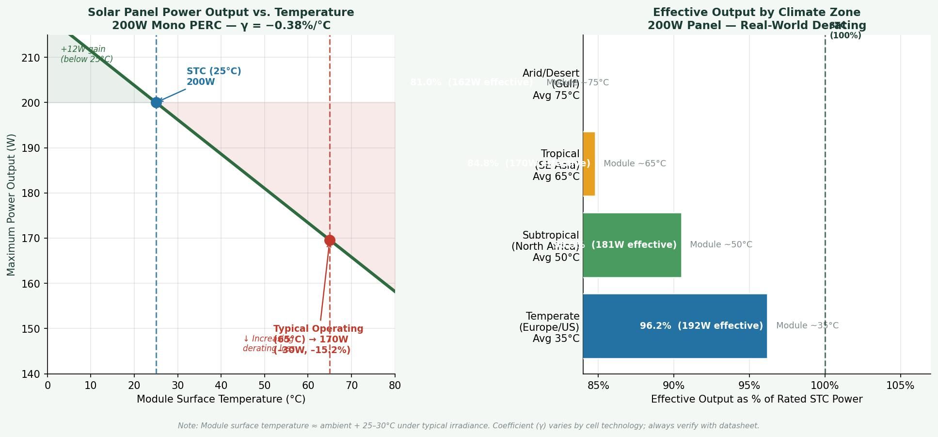
Two specification parameters are frequently underspecified in commercial tenders: the panel's power temperature coefficient and its degradation warranty. In hot climates—where ambient temperatures regularly exceed 35°C and module surface temperatures can reach 65–75°C—every 1°C rise above STC reduces output by approximately 0.35–0.45% for standard monocrystalline cells. A 200W panel specified at STC may deliver only 170–180W at operating temperature in a tropical environment, directly impacting the daily energy budget. Reputable panel manufacturers typically warrant ≤0.45%/year output degradation; panels warranting ≤0.4%/year should be preferred where available.
Key standard to reference: IEC 61215 (design qualification for crystalline silicon PV modules) and IEC 61730 (safety qualification). Always request valid test certificates from an accredited laboratory.
2. Energy Storage: Battery Technology and Sizing
Battery selection is, by a significant margin, the most consequential component decision in solar street lighting system design. It determines both system reliability and total project cost over the service life.
Three chemistries are commercially used in this application: lead-acid gel (VRLA), lithium iron phosphate (LiFePO₄), and ternary lithium (NMC). Engineers working on commercial municipal projects generally favour LiFePO₄ for the following reasons. First, its cycle life at 80% depth of discharge (DoD) is typically 2,000–4,000 cycles—compared to 400–700 cycles for gel batteries at the same DoD. Second, LiFePO₄ has superior thermal stability: it does not enter thermal runaway under overcharge conditions that would compromise gel or NMC cells. Third, its flat discharge curve (voltage remains relatively stable between 20% and 80% state of charge) simplifies controller design and protects LED driver electronics from voltage fluctuation.
Battery capacity sizing is determined by the energy autonomy requirement—the number of consecutive overcast days the system must operate at full or partial power without solar recharge. The engineering standard for main road and arterial applications in tropical monsoon regions (Southeast Asia, West Africa, South Asia) is a minimum of three autonomous days at 80% DoD. At this sizing, the battery is neither chronically under-charged (which degrades cycle life) nor so oversized that capital cost is wasted.
Sizing formula: Required battery capacity (Wh) = (LED wattage × operating hours per day × autonomy days) ÷ system efficiency factor (typically 0.85–0.90). Always state the assumed DoD ceiling in design documents.
3. MPPT Charge Controller: The System's Energy Manager
The charge controller regulates energy flow between the solar panel, battery, and load. In commercial solar lighting system design, Maximum Power Point Tracking (MPPT) controllers have largely superseded Pulse Width Modulation (PWM) controllers for systems above 50W, for a straightforward reason: MPPT algorithms dynamically adjust the operating voltage to extract maximum available power from the panel at any given irradiance level, recovering approximately 20–30% more energy than PWM in real-world partial shade and morning/evening low-irradiance conditions.
Beyond charging algorithm, engineers should verify: the controller's input voltage ceiling (must exceed the panel's open-circuit voltage at minimum operating temperature, with a safety margin), load output voltage compatibility with the chosen LED driver, and whether the dimming protocol (PWM signal, 0-10V analogue, or DALI) matches the luminaire's driver. In larger commercial deployments, controllers with remote monitoring capability—typically via GPRS or NB-IoT—enable data-driven preventive maintenance and are increasingly specified in municipal contracts in ASEAN and GCC regions.
4. LED Luminaire and Driver: The Light Output Subsystem
The LED luminaire converts stored electrical energy into road illumination. Three parameters define its performance in a commercial solar LED system context. First, system efficacy: at the time of writing, quality commercial LED street light fixtures achieve 150–180 lm/W at rated current; products below 130 lm/W impose a direct energy penalty that must be compensated by larger panels and batteries. Second, photometric distribution: road lighting applications require a Type II, III, or IV distribution pattern (per IES classification) to maximise uniformity and minimise glare; verifying this through an independently tested IES photometric file is standard practice for projects targeting IES RP-8 or EN 13201 compliance. Third, thermal management: LEDs degrade faster at higher junction temperatures; luminaires using copper-core PCBs or vapour-chamber heat pipes maintain junction temperature below 85°C in ambient conditions up to 45°C, whereas poorly designed aluminium housings may allow junction temperatures to exceed 100°C.
The LED driver—the electronic power supply for the LED module—warrants separate scrutiny. In solar applications, the driver must accept a DC input voltage range compatible with the battery's discharge curve (e.g., 22–29V for a nominal 24V LiFePO₄ system). Drivers from established manufacturers typically specify an efficiency of ≥93% and carry IP67 or IP68 ratings when installed in the luminaire housing. An important operational advantage of external drivers (versus fully integrated units) is field replaceability: if the driver fails, a technician can swap the unit on the pole without dismounting the optical assembly—a maintenance time saving that is meaningful in large municipal networks.
5. Mounting Structure and Pole Engineering
In commercial solar street lighting projects, the structural system—pole and mounting bracket—is frequently underspecified relative to its importance. Pole design must account for the combined wind load of the solar panel (which acts as a large sail) and the luminaire arm, calculated to the local wind zone standard (ASCE 7, EN 40, or the national equivalent). For panels larger than 200W mounted at typical heights of 6–10 metres, pole wall thickness and foundation bolt circle diameter are project-specific calculations, not catalogue values. Engineers advise requesting structural load calculations from the vendor or performing an independent check when panel area exceeds 1.2 m².
Hot-dip galvanisation (HDG) to ISO 1461 or equivalent is the minimum corrosion protection standard for coastal and high-humidity installations; zinc coating thickness of ≥85 µm is typically specified for marine-proximate sites. Powder-coat finishing over HDG provides additional UV and chemical resistance.
6. System Integration and Monitoring
A commercial solar street lighting system performs as its weakest link. System integration quality—how the six subsystems are physically connected, protected against moisture and thermal cycling, and monitored—determines whether a well-specified BOM translates into reliable field performance.
Key integration requirements include: IP65 minimum (IP67 preferred in flood-prone regions) for all outdoor electrical connections and cable glands; UV-resistant wiring rated for the maximum expected surface temperature; battery enclosures with adequate ventilation or thermal management to prevent heat accumulation in high-ambient-temperature environments; and clearly labelled, accessible maintenance points. For municipal fleets of more than 100 luminaires, remote monitoring via a centralised management system (CMS) with per-node fault detection, energy logging, and dimming control is considered best practice in the Gulf Cooperation Council and in several ASEAN national programmes as of 2024.
Regional Design Context: Southeast Asian Mid-Irradiance Urban Road Project
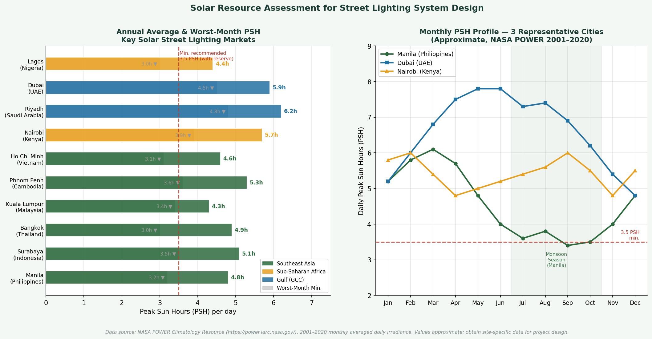
To illustrate how component specifications interact in practice, consider a representative project scenario: a 4-lane secondary urban road in a mid-irradiance city in Southeast Asia (e.g., Metro Cebu, Philippines; Johor Bahru, Malaysia; or Surabaya, Indonesia). Based on NASA POWER historical data, this region typically records 4.5–5.2 Peak Sun Hours (PSH) per day, with June–August monsoon months reducing this to 3.0–3.8 PSH on average. A well-designed system must sustain full illumination during these low-radiation months.
A typical commercial specification for this scenario would include: a 200–250W monocrystalline PERC panel (25% oversizing relative to worst-month demand), a 48V / 100Ah LiFePO₄ battery bank (~4,800 Wh usable at 80% DoD), an MPPT controller rated for ≥15A charge current, and a 60–80W LED luminaire achieving ≥150 lm/W—producing 9,000–12,000 lm at the fixture. This configuration provides approximately 3.5 autonomous days during the monsoon period and meets EN 13201 Class ME3 or ME4 road illuminance targets on a 30–35 metre pole spacing.
Data source: NASA POWER Climatology Resource for Agroclimatology (https://power.larc.nasa.gov/), monthly averaged daily solar irradiance, 2001–2020 climatology. PVGIS (EU JRC) provides equivalent data for Africa, Europe, and the Middle East.
System Selection Guide: Commercial Solar Street Lighting — Configuration Comparison
The table below compares four commonly encountered solar street lighting system configurations across key engineering and procurement dimensions. The intent is to assist engineers and procurement managers in matching system type to project requirements, not to endorse any specific product tier.
Table notes: PSH = Peak Sun Hours; DoD = Depth of Discharge; CapEx ranges are indicative and will vary by region, order volume, and specification. Always obtain project-specific quotations.
Procurement and Acceptance Checklist: 10 Critical Verification Points
The following checklist is designed for use by procurement teams during bid evaluation and by site engineers during goods receipt inspection. Each item corresponds to a component decision discussed in this guide.
Calculation Example: Battery Capacity Sizing for a 70W Commercial Solar LED System in a 4.5 PSH Environment
The following worked example demonstrates the standard engineering approach to battery sizing. All assumptions are stated explicitly; adjusting any one of them will change the result proportionally.
Assumed Conditions:
- Location: Mid-irradiance tropical city, worst-month PSH = 3.5 hours/day (e.g., monsoon period)
- LED luminaire wattage: 70W (including driver losses)
- Operating hours per night: 11 hours (6 PM – 5 AM)
- Required autonomy: 3 consecutive overcast days (zero solar input)
- Maximum DoD: 80%
- System efficiency factor (wiring, controller, battery charge/discharge losses): 0.85
- Battery chemistry: LiFePO₄, nominal voltage 48V
Step 1: Daily Energy Demand
Daily load = 70W × 11 hours = 770 Wh per night
Step 2: Total Energy Reserve Required (3 Autonomy Days)
Total reserve = 770 Wh × 3 days = 2,310 Wh
Step 3: Gross Battery Capacity Required (accounting for DoD ceiling and efficiency)
Gross capacity = 2,310 Wh ÷ (0.80 DoD × 0.85 system efficiency) = 2,310 ÷ 0.68 ≈ 3,397 Wh
Step 4: Battery Capacity in Ah (at 48V nominal)
Capacity = 3,397 Wh ÷ 48V ≈ 71 Ah → round up to standard size: 80 Ah at 48V
Step 5: Solar Panel Size Check (verify panel can recharge in available PSH)
Required daily recharge energy = 770 Wh ÷ 0.85 ≈ 906 Wh. At worst-month PSH of 3.5 hours: Required panel output = 906 Wh ÷ 3.5 h ≈ 259W at STC. Apply temperature derating (–15% for 65°C module temperature): 259W ÷ 0.85 ≈ 305W. → Specify a 300–320W monocrystalline panel as the minimum for this scenario.
Conclusion:
For this 70W system in a 3.5 PSH worst-month environment, a 48V/80Ah LiFePO₄ battery and a 300–320W panel represent the minimum commercially robust specification. Vendors proposing a 200W panel and 60Ah battery for this duty cycle are not meeting the 3-day autonomy standard—a discrepancy that should trigger a request for the vendor's own design calculation documentation.
Summary: Two Engineering Principles for Reliable Commercial Solar Street Lighting
The majority of solar street lighting failures in the commercial segment trace back to two root causes: undersized energy storage that cannot sustain three or more days of autonomous operation in low-irradiance periods, and battery chemistry (typically gel or low-grade lithium) that degrades rapidly in high-temperature operating environments. When procurement decisions are driven by these two criteria—verified autonomy reserve and documented cycle-life data from the battery manufacturer—project outcomes improve substantially, regardless of which specific brands are specified.
When a project requires outdoor solar lighting engineering design support, component validation, or custom system configuration for municipal, highway, or industrial solar street lighting applications, Infralumin technical team is available to assist with site-specific system sizing and specification review.
References
- International Energy Agency (IEA) · Off-Grid Renewable Energy Statistics 2023 · 2023 · https://www.iea.org/data-and-statistics
- NASA POWER (Prediction of Worldwide Energy Resources) · Climatology Resource for Agroclimatology · Data portal: https://power.larc.nasa.gov/
- European Commission Joint Research Centre (JRC) · PVGIS Photovoltaic Geographical Information System · https://re.jrc.ec.europa.eu/pvg_tools/
- International Electrotechnical Commission · IEC 61215: Terrestrial Photovoltaic (PV) Modules — Design Qualification and Type Approval · Edition 2: 2021
- International Electrotechnical Commission · IEC 61730: Photovoltaic (PV) Module Safety Qualification · Edition 2: 2023
- International Electrotechnical Commission · IEC 62133: Secondary Cells and Batteries — Safety Requirements for Portable Sealed Lithium Systems · 2017
- Illuminating Engineering Society (IES) · RP-8-18: Recommended Practice for Design and Maintenance of Roadway and Parking Facility Lighting · 2018
- European Committee for Standardization (CEN) · EN 13201: Road Lighting — Parts 1–5 · 2015–2016

Zhongshan Lumin Technology Co., Ltd. is a renowned high-tech enterprise specializing in the research, development, and manufacturing of industrial LED lights.
Contact
@2026 Zhongshan Lumin Technology Co., Ltd.