


Best Practices for Installing Solar Street Lights: A Complete Field-Tested SOP Guide
Infralumin Technical Team · Solar Street Light Engineers · Updated March 2025 · 14 min read
A solar street light is only as reliable as its installation. Over years of supplying off-grid solar lighting systems across Sub-Saharan Africa, Southeast Asia, and the Middle East, we have seen well-specified luminaires underperform simply due to avoidable installation errors — a panel tilted in the wrong direction, a concrete foundation poured below the minimum depth, or a controller commissioned without confirming battery state-of-charge first.
This guide is not a generic overview. It is a distillation of the standard operating procedures (SOPs) we ship with every Infralumin solar street light order, structured so that your installation crew — or your subcontractor — can follow them sequentially on-site without needing to contact support.
How to Use This Guide
All SOP steps are numbered and actionable. Items marked ★ in the commissioning checklist are critical — a "No" response on any starred item requires corrective action before the installation is accepted.
1. Why Proper Street Light Installation Determines System Lifespan
Integrated solar street lights — the all-in-one design where panel, battery, controller, and LED head are housed together — have become the dominant product category for off-grid road lighting. Their installation tolerances are tighter than conventional grid-tied streetlights, for three reasons:
- Panel angle affects charging yield by up to 30%. A panel tilted 15° away from optimal loses roughly one-third of potential daily solar irradiation in equatorial climates.
- Pole inclination loads the hinge bracket. If the pole is not plumb, wind-induced oscillation concentrates stress on the lamp arm weld, a common cause of premature structural failure.
- Battery depth-of-discharge (DoD) is set on day one. If the battery is not at the correct charge level when the controller is first configured, the low-voltage cut-off threshold will be calibrated against an incorrect baseline, degrading cycle life.
Our Field Observation
In post-installation audits of 1,200+ units across six countries, panels installed at the wrong tilt accounted for 41% of "insufficient brightness" complaints in the first year — more than lamp failure, battery degradation, or controller faults combined.
2. Solar Panel Orientation & Tilt Angle: Getting It Right
2.1 Orientation (Azimuth)
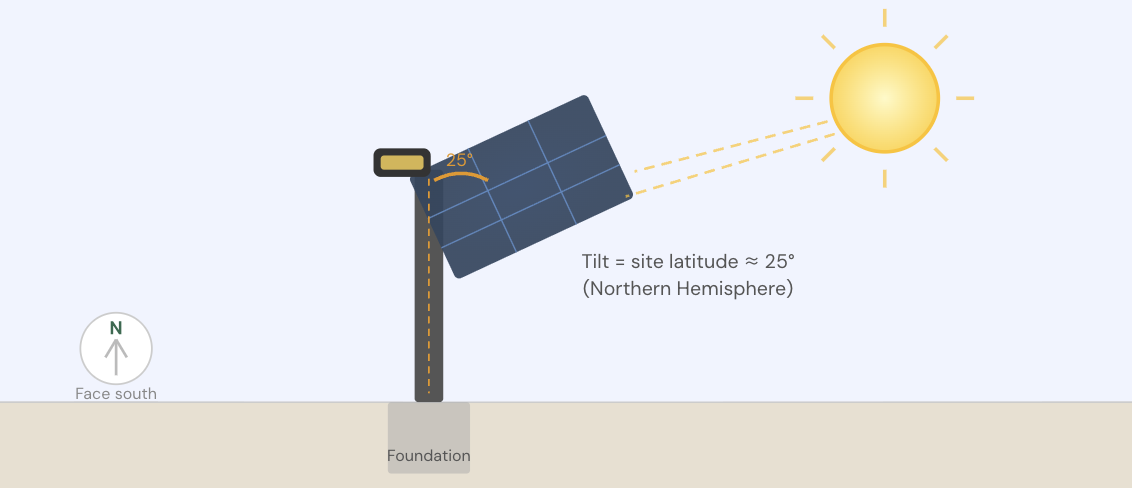
The panel must face the equator. In the Northern Hemisphere, orient the panel due south (azimuth 180°). In the Southern Hemisphere, orient the panel due north (azimuth 0°/360°). A magnetic compass is sufficient for field orientation — GPS azimuth tools are more accurate but rarely available on rural sites.
⚠️Common Mistake
On all-in-one solar street lights, the installer sometimes orients the road side of the lamp head forward and assumes the panel faces the correct direction automatically. This is incorrect. The panel azimuth must be confirmed independently of lamp head orientation.
2.2 Tilt Angle (Elevation)
The optimal tilt angle for maximum annual energy yield is approximately equal to the installation site's geographic latitude. However, for all-in-one solar street lights, which have a fixed tilt bracket, the following simplified table applies:
| Latitude Band | Example Countries/Regions | Recommended Panel Tilt | Acceptable Range |
|---|---|---|---|
| 0° – 10° | Singapore, Kenya, Ecuador | 10° | 8° – 15° |
| 10° – 20° | Ghana, Bangladesh, Mexico City | 15° | 12° – 20° |
| 20° – 30° | Saudi Arabia, India (north), Brazil | 25° | 20° – 30° |
| 30° – 40° | Morocco, China, USA (southwest) | 35° | 30° – 40° |
| 40° – 50° | France, Kazakhstan, Canada | 45° | 40° – 50° |
Infralumin all-in-one solar street lights ship with a pre-set 15° bracket as default. If your site latitude requires a different angle, specify this at order time — we manufacture bracket options at 10°, 15°, 25°, and 35°. Post-installation angle adjustment is not possible without replacing the bracket.
2.3 Shading Assessment
Conduct a shading assessment at the proposed pole location before breaking ground. Walk the site at 10:00 and 14:00 local solar time. If any tree, building, or overhead cable casts a shadow on the panel during these hours, relocate the pole or prune the obstruction. Even partial shading on one panel cell reduces the entire panel's output due to the series-connected bypass diode architecture.
3. Foundation Excavation, Anchor Bolt & Pole Installation SOP
The foundation is the most labor-intensive part of the installation and the one most frequently under-specified by local subcontractors trying to reduce concrete costs. Under-dimensioned foundations cause pole tilt within 12–18 months in soft or sandy soils — a warranty situation that is entirely preventable.
3.1 Foundation Specification by Pole Height
| Pole Height | Excavation Depth | Excavation Width | Anchor Bolt Circle Dia. | Bolt Size | Min. Concrete Grade |
|---|---|---|---|---|---|
| 4 m | 700 mm | 400 mm × 400 mm | 160 mm | M16 × 600 mm | C20 |
| 5 m | 800 mm | 450 mm × 450 mm | 180 mm | M16 × 700 mm | C20 |
| 6 m | 900 mm | 500 mm × 500 mm | 200 mm | M20 × 800 mm | C25 |
| 7 m | 1,100 mm | 550 mm × 550 mm | 220 mm | M20 × 900 mm | C25 |
| 8 m | 1,300 mm | 600 mm × 600 mm | 250 mm | M24 × 1,000 mm | C30 |
⚠️Soft Soil Adjustment
In sandy, laterite, or high water-table soils, increase excavation depth by 25% and use a 4-bolt anchor cage with rebar ties rather than individual J-bolts. Consult the project geotechnical report if available.
3.2 Step-by-Step Street Light Foundation SOP
1. Mark the pole centerpoint.
Use stakes and string line to mark the centerpoint. Confirm clearance from road edge (minimum 500 mm from asphalt edge for roads <6 m wide; 800 mm for wider roads).
2. Excavate to specified depth.
Use mechanical auger where possible. Clear all loose material from the base. If standing water is present, dewater before pouring.
3. Set anchor bolt cage.
Pre-assemble the 4-bolt cage on a flat surface. Lower cage vertically, centering it over the hole using a temporary timber frame. Verify cage is plumb with a spirit level on both axes before any concrete is placed.
4. Route conduit (if applicable).
If the project includes a control cable or remote monitoring wire, lay a 25 mm corrugated conduit from the base of the hole to a trench leading to the controller cabinet before pouring.
5. Pour concrete in lifts.
Pour concrete in two lifts: fill to 50% depth, rod to remove air pockets, then fill to the top. Do not vibrate — rodding is sufficient for these volumes. Trowel the top surface flat.
6. Cure for minimum 72 hours before mounting pole.
Cover with wet burlap in hot, dry conditions. Do not load the anchor bolts until concrete has reached 70% design strength (typically 72 h at >20°C ambient).
7. Mount pole and torque fasteners.
Slide pole base flange over anchor bolts. Install flat washers, spring washers, and nuts in that order. Torque to specification: M16 → 120 N·m; M20 → 240 N·m; M24 → 420 N·m. Use a calibrated torque wrench — not an impact driver.
8. Verify plumb after tightening.
Check pole vertically on two perpendicular axes with a digital inclinometer or accurate spirit level. Maximum allowable deviation:
2 mm per 1,000 mm of pole height
(i.e., ≤ 12 mm lean at top of 6 m pole). Shim as needed before final torquing.
4. Battery, Wiring & Controller Pre-Checks
All-in-one solar street lights arrive with the battery pre-installed in the lamp head. Before mounting the unit on the pole, confirm the following at ground level — it is far more difficult to diagnose electrical issues once the unit is 6 m in the air.
4.1 Battery State of Charge on Arrival
Lithium iron phosphate (LiFePO₄) batteries used in street light units should arrive at ≥ 40% state of charge (SOC). Measure open-circuit voltage at the battery terminals:
| Measured OCV | Approx. SOC | Action |
|---|---|---|
| > 26.0 V (24 V system) | > 80% | ✓ Proceed |
| 24.5 – 26.0 V | 40 – 80% | ✓ Proceed |
| 23.0 – 24.5 V | 10 – 40% | ⚠ Charge before commissioning |
| < 23.0 V | < 10% | ✗ Check for cell damage; contact supplier |
4.2 Wiring Inspection Points
- All MC4 connectors are fully seated and audibly clicked — do not assume a connector is locked by appearance alone.
- Cable entries into the lamp head are sealed with IP67-rated glands. No bare conductor is visible at any gland.
- The PIR/microwave motion sensor lead (if specified) is connected to the designated port on the controller, not the LED driver port.
- The grounding lug on the pole base flange is connected to a grounding electrode ≤ 10 Ω earth resistance (measure with clamp earth tester).
🔴 Critical Safety Note
Never connect the LED driver output to the battery terminals directly to "test the light." This bypasses the controller's over-discharge protection and may permanently damage the battery or trigger thermal runaway.
5 Commissioning & Final Acceptance Checklist
Commissioning is the structured process of confirming that the installed system operates within design parameters before it is handed over to the client or project owner. The checklist below mirrors IEC 60364-6 (Initial Verification) principles adapted for off-grid solar street lighting.
Items marked ★ are critical. A "Fail" on any critical item requires corrective action and re-inspection before acceptance.
Solar Street Light Commissioning & Acceptance Checklist
A. Site & Civil Works
- Pole is plumb: ≤ 2 mm/m deviation verified with inclinometer on 2 axes ★
- Anchor bolt torque recorded and meets specification (M16: 120 N·m / M20: 240 N·m) ★
- Concrete curing period ≥ 72 h confirmed before pole installation date
- Pole spacing matches approved lighting design layout (±0.5 m)
- Road clearance from pole base ≥ 500 mm (local authority requirement may vary)
B. Panel Orientation & Tilt
- Panel azimuth faces equator: south (NH) or north (SH), ± 15° acceptable ★
- Panel tilt angle matches site latitude table ± 5°; recorded on acceptance form ★
- No shading on panel from 09:00 to 15:00 local solar time (observed or modeled)
- Panel surface clean and free of protective film, bird droppings, or transport packaging
C. Electrical & Battery
- Battery open-circuit voltage ≥ 24.5 V (24 V system) or ≥ 12.2 V (12 V system) at time of commissioning ★
- Ground resistance ≤ 10 Ω measured at pole base grounding lug ★
- All MC4 solar connectors fully seated and polarity verified (+ to +, − to −)
- All cable glands sealed; no conductor exposure at lamp head entry points
- Controller charging indicator active during daytime (red/green LED or app confirmation)
- No BMS fault codes present on controller display or mobile app
D. Lighting Performance
- Light activates automatically at dusk (cover panel with hand to simulate): passes ★
- Light output at 100% power matches specified lumen output ± 10% (lux meter @ 1 m nadir) ★
- Dimming schedule (e.g., 100% 18:00–22:00, 50% 22:00–06:00) programmed and verified
- Motion sensor (if specified) triggers brightness boost within 2 seconds of approach
- Light CCT (colour temperature) matches specification (warm 3000K / neutral 4000K / cool 6500K)
E. Structural & Aesthetics
- Lamp arm angle and overhang distance match approved design drawings
- All access panels and maintenance covers closed and secured with tamper-resistant fasteners
- Pole paint/hot-dip galvanizing undamaged; any site scratches touched up with zinc-rich primer
- Serial numbers of lamp unit and pole recorded on project handover sheet
Top 5 Street Light Installation Mistakes and How to Avoid Them
Based on field audit data from 40+ projects, these are the five most frequent installation errors and their fixes:
Mistake 1 — Pouring Concrete Immediately After Rebar Placement
Concrete needs time to consolidate around the anchor bolt cage. Rushing this step (often driven by per-unit day-rate contracts) produces voids around the bolts that become critical failure points. Fix: Make concrete curing a contractual milestone with photographic evidence required before pole erection sign-off.
Mistake 2 — Orienting the Lamp Head, Not the Panel
As noted earlier, the panel azimuth and the lamp head direction are independent on all-in-one designs. Fix: Use a compass app on the panel surface — not the road — before tightening the lamp arm bolt.
Mistake 3 — Over-Tightening the Cable Gland
Installers sometimes overtighten IP glands trying to ensure waterproofing, which splits the inner rubber grommet and actually creates a water ingress path. Fix: Tighten gland until finger-tight, then one additional quarter-turn with a spanner — no more.
Mistake 4 — Commissioning at Midday with a Fully Shaded Panel
Programming the controller while shading the panel to "simulate night" and force the light on is incorrect — the controller's time-keeping reference is calibrated on the first charge cycle. Fix: Allow the unit to go through one natural dusk-to-dawn cycle before adjusting the dimming schedule, or use the manufacturer's mobile app to configure timing directly.
Mistake 5 — Skipping the Grounding Check
Ground resistance testing requires a dedicated clamp tester and takes less than 90 seconds, yet it is omitted on most sites. In lightning-prone environments (common in tropical Africa and Southeast Asia), an inadequate earth path means the controller and LED driver absorb the surge. Fix: Include grounding resistance as a contractual acceptance criterion with a recorded result required on the handover form.
A Reliable Street Light Starts With a Reliable Installation
Every specification in this guide reflects real failure modes that we have observed and corrected on live projects. The commissioning checklist above is derived from the same QC form used by our factory team for pre-shipment inspection — adapted for field use.
If you are planning a solar street lighting project and want factory-level installation support, Infralumin offers project technical consultation, site-specific SOP packages, and on-request training for installation crews.
Infralumin Technical Team
Solar Lighting Engineers · infralumin.com
The Infralumin technical team has designed, manufactured, and deployed off-grid solar street lighting systems since 2012. Our engineers hold certifications in IEC 60364 electrical installation, and our factory is ISO 9001-certified. All installation guidance published on this site is reviewed annually against field audit data from active project portfolios.
Standards & References
- IEC 60364-6:2016 — Low-voltage electrical installations: Verification
- IEC 62446-1:2016 — Grid connected photovoltaic systems: Test, documentation and maintenance
- EN 40-3-1:2013 — Lighting columns: Design and verification
- IESNA RP-8-14 — Roadway Lighting, Illuminating Engineering Society
- World Bank ESMAP (2020) — Off-Grid Solar Market Trends Report

Zhongshan Lumin Technology Co., Ltd. is a renowned high-tech enterprise specializing in the research, development, and manufacturing of industrial LED lights.
Contact
@2026 Zhongshan Lumin Technology Co., Ltd.