


LED Street Light Pole Spacing: How to Compare Layout Options
Choosing LED street light pole spacing involves more than increasing the distance between poles to reduce fixture quantities. Spacing affects road illumination, uniformity, glare, installation requirements and overall project cost. A layout that appears economical may require additional luminaires or redesign if it fails to meet the project's lighting criteria.
For lighting designers, municipalities, EPCs and procurement teams, a more reliable approach is to compare feasible layouts for the same road, verify their performance through photometric calculations and refine the design according to the results.
This guide explains how to compare layout options, identify and correct performance issues, and assess project costs before selecting a suitable arrangement.
There is no single spacing that suits every road. Pole spacing is a starting design variable, not a universal specification. The appropriate layout depends on road geometry, mounting height, luminaire optics and the required lighting criteria, and must be verified before the design is finalised.
What Road and Lighting Data Do You Need Before Comparing Pole Spacing?
Start by establishing a common set of project inputs. Keeping the assumptions consistent helps ensure that differences in calculation results reflect the layout changes rather than inconsistencies in the road model or luminaire configuration.
Collect the following information where available:
Road geometry: Carriageway width, number of lanes, median width, road curvature, junctions, pedestrian crossings and adjacent areas.
Installation constraints: Available pole positions, mounting height, outreach, bracket angle, setbacks, existing foundations and underground utilities.
Lighting requirements: Applicable road or pedestrian lighting class, required performance criteria and additional requirements in the tender or project specification.
Luminaire data: Proposed model, wattage, optical distribution, photometric file and installation orientation.
Operating assumptions: Maintenance factor, expected operating hours, dimming schedule and maintenance arrangements.
Confirm whether the project requires a luminance-based or illuminance-based assessment. The appropriate method depends on the road category, applicable standard and project requirements.
If some information is not yet confirmed, record it as a provisional assumption. This makes it easier to identify which parts of the calculation need to be reviewed when more detailed project data becomes available.
How Do Mounting Height, Optics and Pole Arrangement Affect the Options?
Pole spacing should be evaluated alongside mounting height, luminaire optics and pole arrangement. These variables interact, so changing spacing alone will not necessarily resolve uniformity or glare problems.
Mounting height and spacing ratio
A useful preliminary indicator is the ratio of pole spacing to mounting height:
Spacing-to-height ratio = pole spacing ÷ mounting height
For example, a spacing of 30 m with a mounting height of 10 m gives a ratio of 3.0. This can help designers screen and compare initial layouts, but it is not a universal design limit or evidence of compliance. The suitability of the arrangement depends on road geometry, optical distribution and the required lighting criteria.
Mounting height should also be considered in relation to road width, the lighting application and the selected luminaire's light distribution. For more guidance on the factors that influence pole height, see our guide to street light pole height.
Optical distribution
Two LED street lights with similar wattage can produce different lighting patterns. The selected optic influences how light reaches the carriageway, including the areas between poles and across the road width. A wider spacing may be feasible with one optical configuration but unsuitable with another.
Review the photometric data for the actual luminaire model and optical variant rather than relying on wattage or nominal lumen output alone.
Pole arrangement
Common arrangements include:
Single-sided: Poles are installed along one side of the road. This may simplify installation, but road width and light distribution can limit performance.
Staggered: Poles alternate between opposite sides of the road. Depending on the geometry and optics, this arrangement may improve distribution across the carriageway.
Opposite-side or symmetrical: Poles face each other across the road. This creates a different distribution pattern but may involve additional civil works and coordination.
These are options to evaluate, not universal recommendations. Existing pole positions, medians, driveways, utilities and roadside obstructions may rule out certain arrangements before photometric calculations begin.
For project-specific product options, see Infralumin's project LED street lighting range.
How Can You Build Comparable Layout Scenarios for the Same Road?
A fair comparison starts with the same road geometry and project requirements. Develop a small set of practical scenarios, keep the baseline assumptions consistent and document any changes between options.
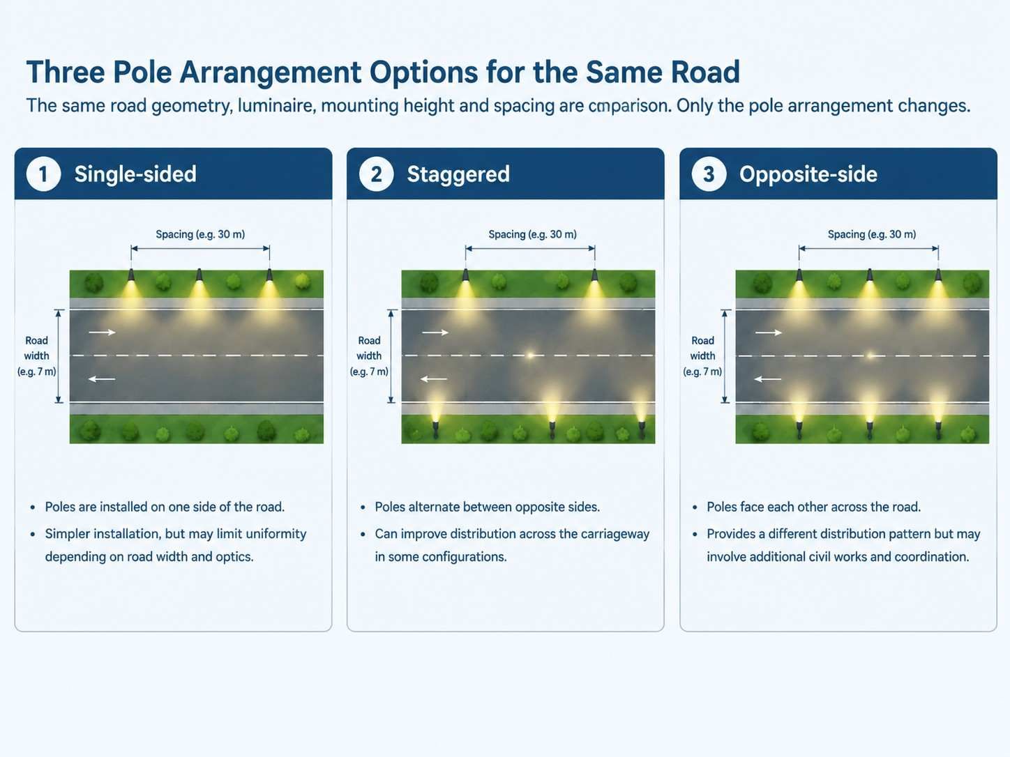
Step 1: Establish a common baseline
Record the road dimensions, target lighting criteria, mounting conditions, proposed luminaire and maintenance assumptions. Keep these consistent across the initial scenarios wherever practical.
Step 2: Develop and compare three layout options
Consider a hypothetical municipal road lighting project with a 7 m-wide carriageway and an initial mounting height of 10 m. These dimensions illustrate the comparison process; they are not general design recommendations.
The project team could assess three options:
| Comparison item | Option A: Closer spacing | Option B: Wider spacing | Option C: Alternative arrangement |
|---|---|---|---|
| Pole arrangement | Baseline arrangement | Same as Option A for the initial spacing test | Staggered or another feasible arrangement |
| Spacing | Reduced | Increased | Determined by the proposed layout |
| Luminaire and optic | Keep the same for the initial test | Keep the same for the initial test | Record any changes |
| Mounting conditions | Keep consistent where practical | Keep consistent where practical | Record any changes |
| Photometric performance | Calculate against all required criteria | Calculate against all required criteria | Calculate against all required criteria |
| Site feasibility | Check proposed pole positions and services | Check proposed pole positions and services | Check both sides of the road and associated constraints |
| Cost | Estimate after technical and site screening | Estimate after technical and site screening | Estimate after technical and site screening |
This table is a comparison framework, not a prediction that any option will pass. Record the actual calculation results and identify which criteria are met or missed before ranking the scenarios.
To isolate the effect of pole spacing, first keep the luminaire, optic, mounting height and road model unchanged wherever practical. Then test integrated alternatives involving a different pole arrangement, mounting configuration or optical distribution. Document each change so that the results remain interpretable.
Step 3: Screen out infeasible options
Before detailed photometric assessment and cost comparison, check each scenario against physical and project constraints:
Can poles be installed at the proposed positions?
Are the mounting arrangements compatible with available space and infrastructure?
Does the proposed luminaire configuration suit the road geometry?
Can the option be assessed against the project's specified lighting criteria?
Remove options that cannot reasonably be implemented and document the reasons. Send the remaining scenarios for photometric verification.
The aim is to identify feasible layouts that meet the project requirements, rather than simply selecting the option with the fewest poles.
How Should You Verify Each Option with Photometric Calculations?
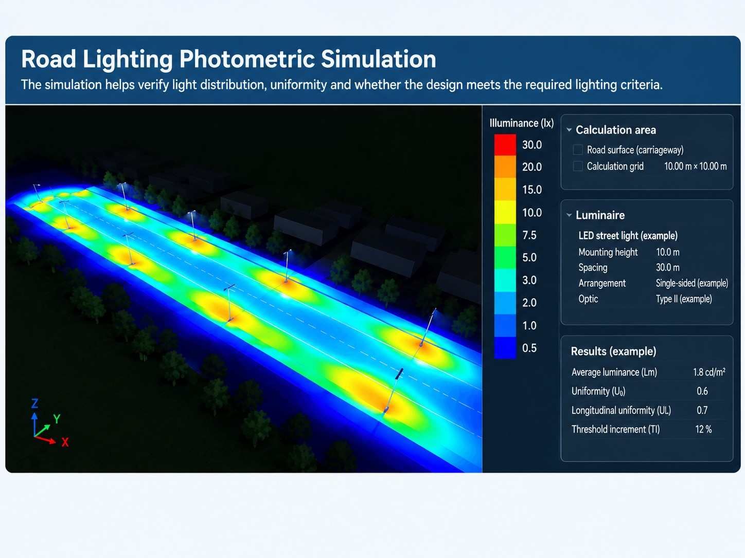
Photometric calculations establish whether a proposed layout can meet the project's specified lighting performance. They also help identify where a design falls short and which variables may need adjustment.
For an introduction to the calculation workflow, see Road Lighting Calculation: How to Verify Road Lighting Performance with DIALux.
Step 1: Verify the calculation inputs
Before comparing results, confirm that the model uses:
The correct road geometry and calculation areas.
The actual proposed mounting height, pole spacing, arrangement and bracket settings.
The correct IES or LDT photometric file for the selected luminaire and optical configuration.
Appropriate road surface and reflection assumptions, where applicable.
The specified maintenance factor and relevant calculation conditions.
A calculation based on the wrong optic or an outdated layout does not verify the proposed installation, even if the reported figures appear reasonable.
Step 2: Define the required lighting criteria
Use the lighting class and performance requirements specified for the project. Depending on the applicable assessment method, these may include:
Average road luminance or illuminance.
Overall or longitudinal uniformity.
Glare-related criteria, such as threshold increment (TI), where applicable.
Lighting requirements for adjacent areas or pedestrian zones.
Do not assess a design using average illuminance or luminance alone. A layout may achieve the required average while still producing excessive variation between bright and dark areas or failing another specified criterion.
Check the applicable standards for your project location
The calculation method and acceptance criteria should reflect the country, road authority and project specification.
For European projects, check the applicable national adoption of the EN 13201 road lighting series. The CIE 140:2019 road lighting calculation report is also a relevant technical reference.
For North African and South American projects, confirm the national standards, municipal requirements and tender specifications applicable to the specific project location. In Brazil, for example, check the applicable ABNT NBR 5101 requirements alongside relevant luminaire conformity and procurement requirements. Other markets may use different standards or approval processes.
Confirm the required lighting class, calculation method, assessment criteria and documentation before finalising the comparison. Meeting one market's criteria does not automatically establish compliance in another.
Step 3: Classify the results and identify the cause of failure
Compare every scenario against each required criterion. Use a consistent decision framework:
| Calculation outcome | Decision | Next action |
|---|---|---|
| All required criteria are met | Pass for the next review stage | Confirm the inputs, documentation and site constraints |
| One or more criteria are not met, but a feasible adjustment may help | Revise and recalculate | Identify the failed metric and test a targeted change |
| Important criteria remain unmet, or the layout is not feasible | Reject or redesign | Test a materially different arrangement or remove the option from the shortlist |
When a scenario fails, identify the specific criterion rather than treating the calculation as a single pass-or-fail result. Review the calculation grid and light distribution to locate the problem, then assess which design variables could reasonably affect it.
Step 4: Adjust the design and recalculate
Choose the adjustment according to the failed criterion:
Average luminance or illuminance is too low: Review luminaire output, optical distribution, mounting conditions and spacing. Increasing output alone may not solve a distribution problem.
Uniformity is insufficient: Inspect darker areas between poles or across the carriageway. Test closer spacing, a different optic, adjusted mounting conditions or an alternative pole arrangement.
Glare criteria are not met: Review the applicable glare metric, luminaire intensity distribution, installation angle and mounting geometry.
Adjacent-area or pedestrian requirements are not met: Check whether the relevant areas have been modelled and whether the distribution and arrangement are suitable.
Follow a repeatable decision loop:
Identify the failed criterion and its location or likely cause.
Select a targeted design change that is feasible on site.
Update the calculation model to reflect the change.
Recalculate and review all required criteria, not just the one that previously failed.
Retain the revised option only if it meets the requirements and remains practical to install. Otherwise, revise again or reject it.
Document all modified variables when testing integrated changes. An adjustment that improves uniformity, for example, could also affect glare, energy use or another performance measure.
A calculation pass is an important technical checkpoint, but it does not replace checks of the final specifications, installation conditions or other project approval requirements.
How Do Pole Spacing Choices Affect Fixture Quantities and Project Cost?
Wider pole spacing may reduce the number of poles and luminaires, but it does not automatically produce the lowest project cost. If a layout fails the lighting criteria, corrective work or redesign may outweigh the initial savings.
Compare costs only after technical and site screening. First identify the options that meet the required lighting criteria and can be implemented within the site's physical and installation constraints. Then compare their costs using the same project scope and assumptions.
For each viable scenario, consider:
Initial installation: Luminaires, poles, brackets, foundations, cabling, trenching, electrical works, installation labour and traffic management.
Operating cost: Expected energy consumption based on actual operating hours and the dimming schedule.
Maintenance: Inspection, cleaning, access requirements, component replacement and expected maintenance arrangements.
Implementation risk: Potential relocations, additional civil works, redesign or remedial installation if the proposed arrangement proves unsuitable.
Keep initial capital cost separate from estimated operating and maintenance costs. If a lifecycle cost comparison is required, use a consistent analysis period, operating profile, energy-price assumption and maintenance basis for every option.
The final comparison should document the proposed arrangement, pole and luminaire quantities, photometric results, site constraints, estimated costs and outstanding risks. This helps the project team distinguish between a layout that is technically compliant and economical to install, and one that appears cheaper only because important requirements have been overlooked.
Where several options meet the requirements, the preferred layout should offer a practical balance of lighting performance, installation feasibility, cost and maintainability.
What Should You Send to Infralumin for a Layout Review?
If you are preparing a municipal lighting project, EPC proposal or road lighting tender, sharing the available project information helps establish which luminaire configurations and layout options are worth evaluating.
Where available, include:
Road drawings or a site plan with dimensions.
Required lighting class, technical specification or tender requirements.
Proposed pole positions, mounting heights and installation constraints.
Existing or preferred luminaire specifications.
Previous photometric calculations and any criteria that were not met.
Project location and relevant local compliance requirements.
If some details are still being finalised, indicate what is confirmed and what remains provisional.
Infralumin supplies project LED street lighting options and can provide relevant product information and photometric files to support lighting calculations. Sharing the project inputs and any existing calculation results gives the team a basis for discussing suitable product configurations and the technical information needed to evaluate alternative layouts.
Contact Infralumin to discuss your LED street lighting project.
Technical References
These references provide technical context. Always confirm the standards and requirements applicable to the specific project and jurisdiction.

Zhongshan Lumin Technology Co., Ltd. is a renowned high-tech enterprise specializing in the research, development, and manufacturing of industrial LED lights.
Contact
@2026 Zhongshan Lumin Technology Co., Ltd.