


How Many Street Lights Does a Road Project Need? A Calculation Guide
Determining how many street lights a road needs is an important part of planning an effective road lighting system. Too few lights can create dark areas and uneven illumination, while excessive installations can increase equipment costs, energy consumption, and maintenance requirements.
The required quantity depends on several factors, including road length, pole spacing, road width, mounting height, luminaire light distribution, and the required lighting performance.
Road length and pole spacing provide a useful starting point for estimating the quantity. However, the final layout should be verified through photometric calculations to ensure it meets the project's requirements.
This guide explains how to calculate street light quantity, which design factors can change the estimate, and how DIALux simulations help verify a road lighting layout.
How to Calculate the Number of Street Lights for a Road
The simplest way to estimate the number of street lights is to divide the road length by the planned spacing between poles. The calculation must also account for the first and last pole positions and the selected installation arrangement.
The Basic Calculation Formula
For a single row of poles along a straight road section, use:
Street Light Quantity Formula
N = ⌈L ÷ S⌉ + 1
L = Road length | S = Pole spacing | N = Number of pole positions
Where:
- Road Length (L): The length of the road section requiring illumination, measured in meters.
- Pole Spacing (S): The maximum planned longitudinal distance between adjacent poles, measured in meters.
- Number of Poles (N): The estimated number of pole positions along one side of the road.
The division is rounded up to the next whole number of intervals. One additional pole is then included for the starting position.
For example, if a 1,000-meter road uses a planned pole spacing of 25 meters:
N = ⌈1,000 ÷ 25⌉ + 1
N = 40 + 1
41 poles
Estimated quantity for one standalone row with a pole at each end.
This calculation assumes a standalone road section with a pole at each end. On continuous roads, shared boundary poles and actual end setbacks may change the number of new poles required.
How Installation Layout Changes the Quantity
The pole arrangement also affects the total number of poles and luminaires.
- Single-sided arrangement: One row of poles is installed along one side. With 25 m spacing over a 1 km standalone section, approximately 41 pole positions are required.
- Opposite-side arrangement: Two rows of poles are installed on opposite sides. If each side independently uses 25 m spacing and has a pole at both ends, approximately 82 pole positions are required.
- Staggered arrangement: Poles alternate between the two sides. If 25 m refers to the longitudinal distance between consecutive poles, alternating from one side to the other, approximately 41 pole positions may be required over the same standalone section. If 25 m is measured between poles on the same side, the total quantity will be different.
For staggered and opposite-side layouts, confirm how spacing is defined in the lighting plan. The distance between consecutive luminaires along the road may differ from the distance between poles on the same side.
Pole quantity and luminaire quantity should also be calculated separately. A twin-arm pole, for example, can carry two luminaires.
Example: Estimating Street Lights for a 1 km Road
Consider a preliminary street lighting estimate with the following assumptions:
| Parameter | Specification |
|---|---|
| Road length | 1,000 m (1 km) |
| Road width | 4–6 m |
| Pole spacing | 25 m |
| Pole mounting height | 6 m |
| Pole arrangement | Single-sided |
| Luminaire power | 51.5 W |
| Luminaires per pole | 1 |
Using the basic formula:
N = ⌈1,000 ÷ 25⌉ + 1 = 41 poles
Assuming one luminaire is installed on each pole, the estimated quantity is also 41 luminaires.
Estimated Connected Lighting Load
41 × 51.5 W = 2,111.5 W
Approximately 2.11 kW
This is a preliminary estimate based on the stated standalone-section assumptions. It does not establish whether the proposed 25 m spacing meets the road's lighting requirements.
The final pole spacing and luminaire configuration should be checked against the road geometry, selected luminaire photometry, and applicable lighting criteria before the equipment schedule is confirmed.
What Factors Affect the Number of Street Lights Required?
Road length and pole spacing provide an initial estimate, but the final quantity depends on road conditions and lighting performance requirements.
Road Width and Required Lighting Performance
Road width affects how light needs to be distributed across the carriageway. A single-sided arrangement may be suitable for some narrow residential roads, while wider roads may require different pole positions, optical distributions, or installation configurations.
The required lighting performance also depends on the road classification and applicable project standards. Depending on the lighting class, the design may need to meet criteria for average road luminance or illuminance, uniformity, glare, and surrounding-area lighting.
A wider road does not automatically require twice as many street lights. The suitable quantity depends on how the selected luminaires perform at the proposed mounting height and spacing.
Pole Spacing, Mounting Height, and Light Distribution
Pole spacing, mounting height, and luminaire photometry work together to determine how effectively light covers the road.
Pole Spacing
Wider spacing can reduce the number of poles and installation costs. However, excessive spacing may create dark areas or insufficient lighting uniformity.
Mounting Height
Mounting height affects the area covered by each luminaire and the distribution of light across the road surface. A higher mounting position does not automatically allow wider spacing; the result depends on the optical design and required lighting performance.
Luminaire Light Distribution
The optical distribution determines how light is directed along the road and across its width. Two luminaires with similar wattage or luminous flux can produce different road lighting results because their photometric distributions differ.
For residential roads, backlight control may also be important when poles are installed close to houses or residential windows.
The proposed spacing should therefore be evaluated using the photometric file of the actual luminaire selected for the project, rather than relying on wattage alone.
Pole Arrangement and Special Road Sections
The arrangement of poles influences both the quantity and distribution of street lights.
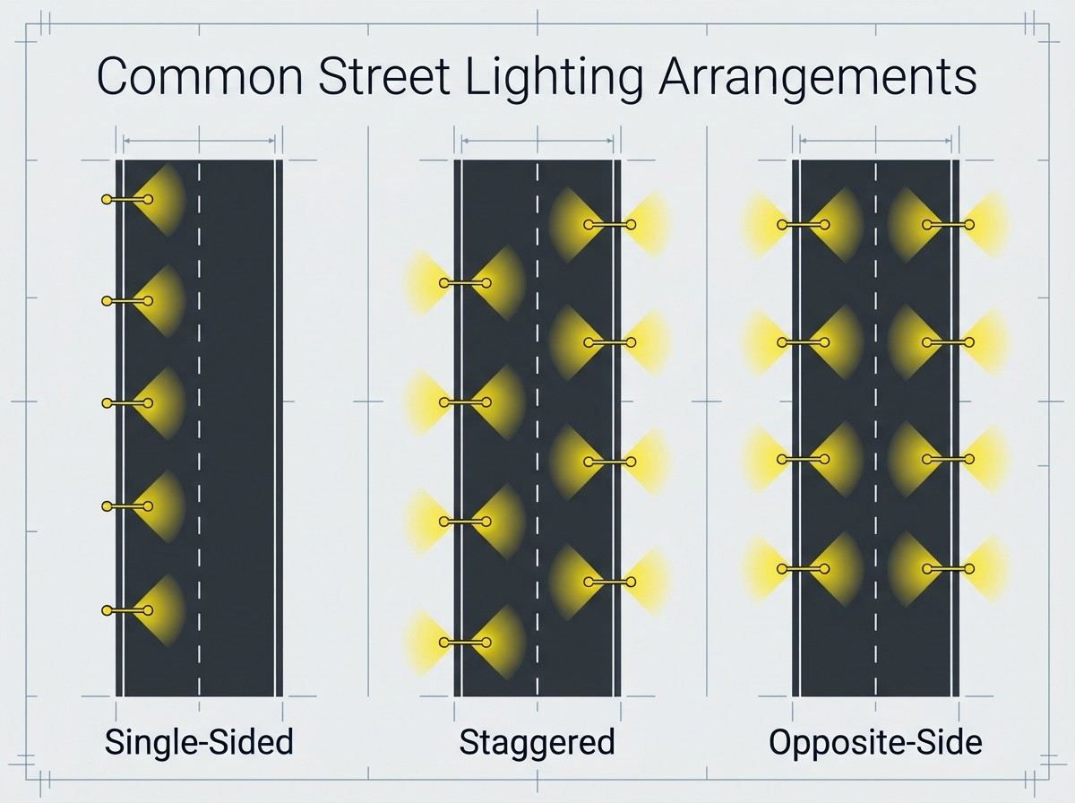
- Single-sided: Poles are installed along one side of the road. This may suit narrower roads or locations with limited installation space.
- Staggered: Poles alternate between both sides, creating a different distribution pattern across the carriageway.
- Opposite-side: Poles are positioned across from each other on both sides. This may be considered for wider roads or specific lighting requirements.
Other locations, such as intersections, roundabouts, pedestrian crossings, curves, bus stops, and bridges, may require additional or repositioned luminaires.
Regular spacing along a straight road may not be suitable for every section. These areas should be assessed separately according to their geometry, visibility requirements, and installation constraints.
How to Verify the Final Street Light Quantity
A preliminary pole count does not guarantee that the proposed layout will provide adequate road lighting. Before finalizing the quantity, the design should be checked against project requirements and actual site conditions.
Check the Layout Against Project Requirements
Review the following information before confirming the lighting layout:
- Road dimensions: Road length, carriageway width, number of lanes, and median dimensions.
- Pole positions: Installation side, spacing, mounting height, and distance from the road edge.
- Luminaire specifications: Input power, luminous flux, photometric distribution, and installation angle.
- Lighting requirements: Applicable road lighting class and required performance criteria.
- Site conditions: Trees, buildings, underground utilities, overhead cables, access points, and other obstructions.
For European road lighting projects, the EN 13201 series provides a framework for road lighting classification, performance requirements, and evaluation methods. The applicable standard edition, national requirements, municipal specifications, and project documents should be confirmed for each project.
Use DIALux to Verify the Proposed Layout
Photometric calculations provide a more reliable way to assess whether the proposed pole spacing and luminaire arrangement meet the required lighting performance.
A typical DIALux simulation uses:
- Road geometry and carriageway width.
- Pole mounting height and spacing.
- Luminaire photometric files, such as IES or LDT files.
- Luminaire orientation and installation angle.
- Road surface characteristics.
- Applicable lighting class and calculation criteria.
The simulation evaluates how light is distributed across the road surface. Depending on the lighting class and project requirements, the results may include average luminance or illuminance, uniformity, glare, and other relevant indicators.
If the calculated results do not meet the project requirements, engineers can adjust pole spacing, mounting height, luminaire distribution, or installation arrangement and run the simulation again.
Example: DIALux Simulation for 4 m and 6 m Residential Roads
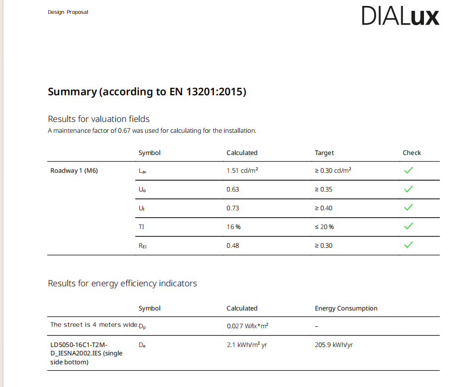
A residential road lighting project provides an example of how road width can affect the performance of the same lighting layout. For this comparison, the project uses the M6 lighting class and the performance targets specified in its design brief.
Two alternatives were modelled for 4 m and 6 m carriageways. Both used the same single-sided arrangement, luminaire configuration, and installation parameters to compare the effect of road width.
Project Design Parameters
| Parameter | Specification |
|---|---|
| Application | Residential roads |
| Road width | 4 m and 6 m |
| Road lighting class | M6 |
| Pole arrangement | Single-sided |
| Pole mounting height | 6 m |
| Pole spacing | 25 m |
| Luminaire power | 51.5 W |
| Luminaire luminous flux | 6,715 lm |
| Maintenance factor | 0.67 |
The DIALux model used a local section with 14 luminaires. This is a simulation input for comparing the two road-width alternatives, not the quantity required for the entire 1 km road.
DIALux Simulation Results
| Performance Indicator | Project Target | 4 m Road | 6 m Road |
|---|---|---|---|
| Average maintained luminance (Lav) | ≥0.30 cd/m² | 1.51 cd/m² | 1.29 cd/m² |
| Overall uniformity (U₀) | ≥0.35 | 0.63 | 0.48 |
| Longitudinal uniformity (Uₗ) | ≥0.40 | 0.73 | 0.81 |
| Threshold increment (TI) | ≤20% | 16% | 15% |
| Edge illuminance ratio (REI) | ≥0.30 | 0.48 | 0.22 |
What the Results Show
4 m road: Meets all five performance targets adopted for this project.
6 m road: Meets four of the five targets. Its REI result of 0.22 is below the specified minimum of 0.30.
This result indicates that the wider road layout does not meet the project's edge-area lighting target, even though its other four reported indicators meet their respective targets. It does not, by itself, mean that the entire road lighting design is inadequate.
The 6 m alternative therefore needs further assessment. Potential adjustments include reviewing the luminaire's light distribution toward the road edges, pole positions, and installation arrangement. The revised layout should then be checked through another photometric simulation.
The comparison highlights the importance of checking road-edge lighting performance when adapting a lighting layout to a wider carriageway.
Get Support for Your Road Lighting Project with Infralumin
Determining the right number of street lights requires balancing road dimensions, lighting performance, installation conditions, and project costs.
Infralumin provides LED street lighting solutions for residential roads, urban streets, and infrastructure projects. Our team can help review luminaire specifications, evaluate pole spacing, and assess suitable lighting configurations for different road layouts.
When preparing your project, sharing the following information can help the engineering team evaluate suitable options:
- Road length and carriageway width.
- Required road lighting class.
- Preferred pole arrangement.
- Pole mounting height and proposed spacing.
- Project location and applicable standards.
Planning a Road Lighting Project?
Discuss your road layout, lighting requirements, and DIALux calculation needs with the Infralumin team.
Contact Infralumin
Zhongshan Lumin Technology Co., Ltd. is a renowned high-tech enterprise specializing in the research, development, and manufacturing of industrial LED lights.
Contact
@2026 Zhongshan Lumin Technology Co., Ltd.