

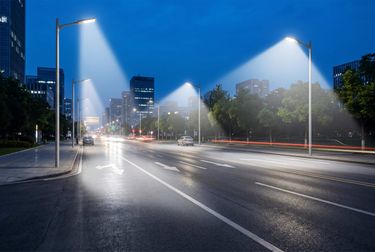
Type II vs. Type III Light Distribution: Choosing the Right Optic for Municipal Street Lights
Imagine walking down a freshly paved municipal road at night. One stretch feels perfectly, evenly lit, making you feel secure and aware of your surroundings. A few blocks later, however, you find yourself squinting through frustrating dark spots or shielding your eyes from blinding overhead glare. The difference between these two experiences rarely comes down to the wattage of the fixtures overhead. More often than not, the culprit is the optical engineering. For procurement teams, municipal engineers, and lighting designers, mastering the nuances of Type II vs Type III light distribution is the ultimate key to designing safe, compliant, and cost-effective roadways. Selecting the wrong lens doesn't just waste energy; it creates hazardous driving conditions and severely inflates your installation budget. So, how do you determine the exact optical footprint required to make your next infrastructure project a success?
Understanding IES lighting patterns
To fully grasp optical selection, we first need to look at how light is controlled and categorized. Out of the box, a raw LED chip emits light in a highly directional but largely uncontrolled manner. Without intervention, this intense, raw light is practically useless for complex infrastructure applications. To solve this, engineers utilize secondary optical lenses—typically molded from high-grade, UV-stabilized polycarbonate or PMMA. These lenses sit directly over the LED arrays, refracting and bending the lumen output to shape the light exactly where the pavement needs it.
The Illuminating Engineering Society (IES) developed a universally recognized classification system to categorize these geometric footprints. IES lighting patterns define how a luminaire distributes light laterally (across the width of the road) and longitudinally (up and down the length of the road). Rather than relying on a basic LED street light beam angle, which only gives you a simplified conical spread, this classification details the exact shape of the illumination zone once the fixture is mounted at a specific height.
The standard distribution types range from Type I, which casts a long, narrow, bidirectional footprint directly under the fixture, all the way up to Type V, which provides a circular, 360-degree footprint ideal for open parking areas. By utilizing photometric software like DIALux or AGI32, lighting designers can take these IES files and accurately calculate the spacing-to-mounting-height ratios. This meticulous planning ensures that every inch of the asphalt meets strict Department of Transportation (DOT) visibility standards without wasting a single lumen on the surrounding environment.
When to use Type II (narrow roads) vs. Type III (wide roadways)
The most common and critical decision lighting professionals face when specifying roadway fixtures is choosing between Type II and Type III distributions. Both are asymmetrical patterns, meaning they are explicitly designed to be mounted at or near the edge of a roadway, pushing light forward onto the driving lanes and outward along the path. However, their lateral reach differs significantly, making them suitable for entirely different infrastructural geometries.
The core distinction lies in the half-maximum candela trace. In practical terms, this measures how far forward the most intense part of the light beam reaches across the road, expressed in multiples of the luminaire's mounting height (MH).
| Feature | Type II Distribution | Type III Distribution |
|---|---|---|
| Lateral Width | 1.0 to 2.25 times Mounting Height | 2.25 to 2.75 times Mounting Height |
| Beam Shape | Long, stretched oval | Broad, expansive oval |
| Ideal Road Geometry | Narrow (1 to 2 lanes) | Wide (3 to 4 lanes) |
| Typical Pole Placement | Single-sided or staggered | Opposite sides, staggered, or median |
| Primary Design Goal | Maximize pole spacing lengthwise | Push light deeply across wide asphalt |
To translate these metrics into real-world municipal planning, consider the following specific application scenarios for each optic:
- Type II Applications: This specialized street light optic is heavily utilized for local residential streets, narrow jogging paths, and single-lane auxiliary roads. Because the light is tightly controlled laterally and stretched longitudinally down the length of the street, municipalities can install poles further apart. This significantly reduces total hardware costs while maintaining excellent uniformity and preventing light from spilling onto adjacent residential lawns.
- Type III Applications: When your project involves wide commercial corridors, multi-lane expressways, or major intersections, Type III is the undeniable standard. It provides a much broader lateral throw, ensuring that the driving lanes furthest from the lighting pole receive adequate, safe illumination. It is also frequently utilized around the perimeter perimeters of large commercial parking lots to project light inward toward the center.
Choosing between the two requires careful analysis of the road's width and the pole's mounting height. Installing a Type III optic on a narrow residential street guarantees that a massive portion of your light will overshoot the pavement. Conversely, placing a Type II fixture on a four-lane highway will leave the center lanes dangerously dim, creating a serious liability for the municipality.
How asymmetric optics minimize light pollution and glare
Modern roadway illumination is no longer just a contest of raw brightness; it is a discipline of precision control. As cities become more densely populated, the demand for dark-sky compliant lighting has surged. This is where the advanced design of asymmetric optics becomes an invaluable asset for urban planners. Unlike older symmetric lenses that indiscriminately throw light in all directions, asymmetric lenses are engineered to direct the vast majority of their output forward and laterally, while severely restricting the light that travels backward behind the pole.
This directional precision directly addresses the three core components of the BUG rating system (Backlight, Uplight, and Glare). By utilizing tailored asymmetric distribution, high-quality fixtures actively combat light pollution and improve community satisfaction. The specific environmental and safety benefits include:
- Elimination of Light Trespass: By minimizing backlight, these lenses ensure that high-lumen street lights do not shine into adjacent residential bedroom windows. This drastically reduces nuisance complaints and improves the overall quality of life for the surrounding community.
- Reduction of Sky Glow: Superior optical designs feature a zero-uplight rating. By keeping 100% of the light directed downward toward the horizontal task plane, these fixtures preserve the night sky, protect nocturnal ecosystems, and comply with strict environmental regulations.
- Improved Visual Comfort: Carefully calibrated lenses reduce high-angle glare, which is the harsh light that strikes a driver's eye directly. Mitigating this glare prevents temporary blinding for motorists and pedestrians, significantly enhancing traffic safety, particularly in wet conditions where asphalt reflectivity spikes.
For these optical advantages to remain effective over time, the physical construction of the housing must be flawless. Even the best lens is useless if it becomes clouded by moisture or cracked by debris. A high-quality luminaire must feature a rugged die-cast aluminum housing and robust environmental protections. High IP ratings (like IP66) and IK ratings (like IK08) ensure that moisture, dust, and physical impacts cannot penetrate the fixture to degrade the internal optical lenses, ensuring the distribution remains precise and glare-free for decades.
Impact of correct optic selection on project cost
It is a common misconception that the financial implications of a lighting project are determined solely by the initial purchase price of the luminaires. In reality, the correct light distribution pattern is one of the most powerful levers a general contractor or project manager has to control the total cost of ownership for a municipal network.
When you match the exact lateral and longitudinal throw of a fixture to the physical geometry of the road, you optimize the pole spacing. Maximizing the distance between poles without sacrificing lighting uniformity means you purchase fewer fixtures and erect fewer steel or aluminum poles. More importantly, it drastically reduces the labor hours required for trenching, pouring concrete bases, and pulling underground copper wiring. For a large-scale highway project, increasing the distance between poles by just a few meters can eliminate dozens of mounting points, saving tens of thousands of dollars in foundational infrastructure costs.
Furthermore, proper optical alignment allows you to achieve the target lux levels on the ground using a lower system wattage. Instead of brute-forcing brightness with a high-wattage led street light that spills wasted lumens into the surrounding environment, a lower-wattage fixture with a highly efficient Type II or Type III lens delivers the light exactly where the DOT requires it. This translates directly into sustained energy savings and a substantially lower carbon footprint over the 15 to 20-year lifespan of the installation.
When these highly efficient optics are paired with modern smart lighting controls—such as NEMA or Zhaga receptacles linked to central management systems—municipalities can push their operational savings even further. Smart systems allow for automated dimming schedules during off-peak traffic hours and provide proactive maintenance alerts, cutting down on unnecessary utility costs and reducing the need for routine maintenance truck rolls.
Conclusion
Navigating the complexities of roadway illumination requires far more than just selecting an adequate wattage; it demands a strategic, highly technical approach to optical engineering. By carefully evaluating the width of your roadways and understanding the distinct geometric advantages of Type II versus Type III distributions, you can dramatically improve civic safety while simultaneously minimizing light pollution and slashing infrastructure costs.
At Infralumin, we leverage years of manufacturing expertise and deep partnerships with top-tier international component brands to deliver exceptional commercial and industrial lighting solutions. With our robust die-cast aluminum housings, innovative tool-free maintenance designs, and comprehensive OEM/ODM customization services, we engineer our fixtures to meet the exact optical demands of your most challenging municipal projects. We don't just supply lights; we provide tailored optical solutions. Reach out to our technical consulting team today to request a custom photometric analysis for your next installation and see the Infralumin difference firsthand.
FAQ
What is the main difference between Type II and Type III distributions?
The primary difference is the lateral reach of the light beam. Type II pushes light 1.0 to 2.25 times the mounting height across the road, making it ideal for narrow, two-lane streets. Type III pushes light much further (2.25 to 2.75 times the mounting height), making it the standard, safer choice for wider, multi-lane roadways and highways.
How does an LED street light beam angle affect road safety?
The angle and subsequent distribution dictate how evenly light is spread across the driving surface. A precisely engineered optical spread ensures uniform illumination without hazardous dark spots or excessive high-angle glare. This uniformity allows drivers to quickly identify pedestrians, debris, or changes in the road layout, reducing reaction times and preventing accidents.
Can I use a Type III optic for a single-lane residential street light?
While it is physically possible to mount the fixture, it is highly discouraged. Using a wide-throw Type III optic on a narrow street results in severe backlight issues and wasted energy. Much of the light will overshoot the pavement and spill onto residential lawns and houses, leading to light trespass complaints and poor overall efficiency.
Why are IES lighting patterns important for municipal lighting?
IES lighting patterns provide standardized, highly predictable mathematical models of how a fixture will distribute light. This allows municipal engineers and lighting designers to conduct accurate photometric software simulations before a single pole is purchased. It guarantees that the final installation will meet strict government safety standards for visibility and uniformity.
What makes a high-quality led street light last longer outdoors?
Longevity relies heavily on thermal management and structural environmental protection. Premium fixtures utilize heavy-duty die-cast aluminum housings with optimized heat sinks to protect internal chips from heat degradation. Additionally, high IP (Ingress Protection) and IK (Impact Protection) ratings ensure the fixture's optical lenses remain sealed against heavy rain, dust accumulation, and mechanical shocks.

Zhongshan Lumin Technology Co., Ltd. is a renowned high-tech enterprise specializing in the research, development, and manufacturing of industrial LED lights.
Contact
@2026 Zhongshan Lumin Technology Co., Ltd.